
Single Point Diamond Turning 1 Section12 Lessons1 Quiz12 Weeks
Lesson 8 – Workholding, Runout, and Chuck Balance
What You Will Learn
- Prepare and clean a vacuum chuck and workpiece mounting surface
- Mount and center a workpiece or reference stud
- Explain how vacuum is used to hold the workpiece
- Measure and reduce spindle runout
- Explain how chuck balance and vibration can affect the finished surface
 Why Workholding Matters
The tool can follow a highly accurate program only if the workpiece is held in a stable and repeatable position. Single point diamond turning commonly uses vacuum workholding because it can secure a flat-backed part without heavy mechanical clamping. Vacuum holding is effective, however, only when the mating surfaces are clean, flat, and free from damage. Even a small particle trapped between the chuck and the workpiece can introduce tilt or runout that becomes part of the machining error. A reliable setup follows a consistent sequence: clean and inspect the mounting surfaces, position the part, establish vacuum, center the workpiece, measure runout, and verify balance before precision cutting begins.
Cleaning the Chuck and Workpiece
The chuck surface and the back of the workpiece should be cleaned with an approved solvent, such as isopropyl alcohol, when appropriate for the materials being used. Both surfaces should also be inspected for burrs, nicks, chips, or other raised defects that could prevent full contact. If permitted by the machine and workholding procedure, a fine honing stone may be used carefully to remove small raised defects from appropriate mounting surfaces. The goal is not to reshape the chuck or change its geometry, but to remove localized high points that interfere with proper seating. Cleaning should always follow the shop’s chemical-handling and material-compatibility requirements. After cleaning, avoid touching precision mating surfaces with bare fingers because oils, moisture, and particles can be transferred back to the interface.
 Applying Vacuum
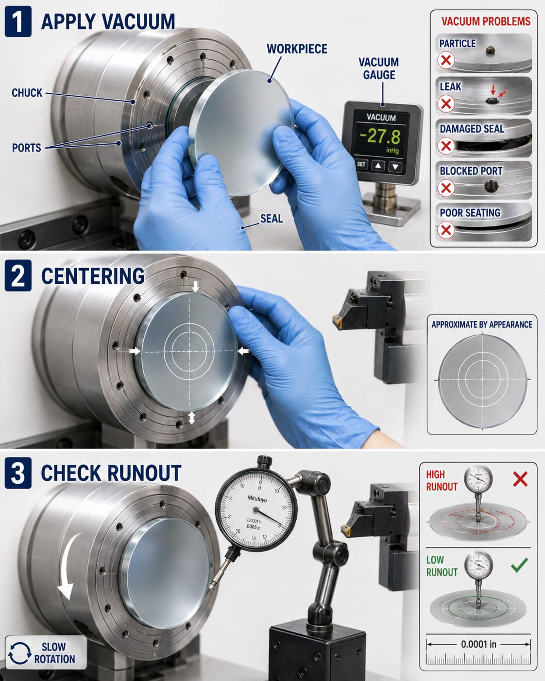
The workpiece is placed gently against the chuck and positioned as close to center as practical before vacuum is applied. Once vacuum is established, the operator should confirm that the indicated vacuum level is within the acceptable range for the machine and workholding system. Vacuum requirements vary by machine, chuck design, part size, seal condition, and material. A lower-than-normal vacuum reading should be investigated rather than ignored. Possible causes include contamination, leaks, damaged seals, blocked passages, poor seating, or an unsuitable workpiece surface. Vacuum should be treated as part of the setup data. A part that appears to remain in place may still be inadequately secured for precision machining or high-speed spindle rotation.
Centering and Runout
After the workpiece is secured, the spindle can be rotated slowly or by hand, when the machine design permits, so that gross runout can be observed. The workpiece may then be adjusted carefully to improve its position before a precision measurement is performed. Runout is the amount by which a mounted surface or reference feature deviates from its intended position as the spindle rotates. It is commonly measured with a dial indicator, lever indicator, or other high-resolution displacement sensor positioned against an appropriate reference surface. As the workpiece approaches the required alignment, progressively finer adjustments and higher-resolution measurements should be used. Precision diamond-turning setups may require runout to be controlled to approximately the micrometer level or below, depending on the part, machine, and operation. A workpiece that appears visually centered is not necessarily centered accurately enough for SPDT. Final alignment should always be based on measurement rather than appearance alone.
Chuck Balance
Once runout has been reduced to an acceptable level, the rotating assembly should be checked for balance. The chuck, workpiece, adapters, fasteners, and other rotating components all contribute to the mass distribution around the spindle axis. If the mass is unevenly distributed, centrifugal forces increase as spindle speed rises and can produce vibration. Some SPDT systems include a balance-measurement function or dedicated balancing routine that identifies the magnitude and direction of the imbalance. Balance is typically improved through small, controlled adjustments to designated balance screws, weights, or other correction features. After each adjustment, the spindle is run again and the vibration or imbalance is remeasured. This process is repeated until the measured response is within the acceptable range. Balance corrections should be based on measured results rather than guesswork. Large or uncontrolled adjustments can make the imbalance worse or introduce a new source of error.
Vibration and Surface Quality
An unbalanced rotating assembly produces cyclic forces that can move the spindle, workpiece, tool, or machine structure relative to one another. Because the disturbance repeats with spindle rotation, it can create a repeating pattern on the finished surface. In conventional machining, a small amount of vibration may have little effect on whether a part meets its tolerance. Optical surfaces are much less forgiving. Extremely small periodic motions can produce visible or measurable waviness, form error, or surface texture. Vibration can also originate from bearings, motors, pumps, floor motion, loose components, or nearby equipment, so balance is not the only possible cause. However, proper chuck and workpiece balance eliminates one important source before machining begins. Good workholding therefore depends on four related conditions: clean mounting surfaces, reliable vacuum, low runout, and good rotational balance. These conditions should be established before the first precision cut. Attempting to compensate for a mechanical setup problem with CNC offsets may change where the tool cuts, but it does not remove the underlying source of instability.
This interactive demonstrates how workholding conditions affect vibration and the finished optical surface. By changing balance, runout, vacuum, and cleanliness, you can see how small setup problems create repeating surface errors. It also shows why CNC offsets cannot correct vibration caused by a mechanical setup problem.