
SPDT cutting quality is controlled by a combination of variables rather than by one ideal machine setting. Spindle speed determines how quickly the workpiece rotates, feed rate determines how quickly the cutting tool advances, depth of cut determines how much material is removed during each pass, and the tool nose radius influences the geometry of the cut. These parameters interact with material properties, tool rake angle, machine stiffness, coolant conditions, and the geometry of the part.
Because materials respond differently to diamond cutting, there is no single combination of speed, feed, and depth of cut that works for every application. Aluminum, brass, nickel, acrylic, germanium, silicon, zinc selenide, and zinc sulfide all have different mechanical, thermal, and fracture characteristics. Cutting conditions should therefore be selected for the specific material, machine, tool geometry, and surface requirements.
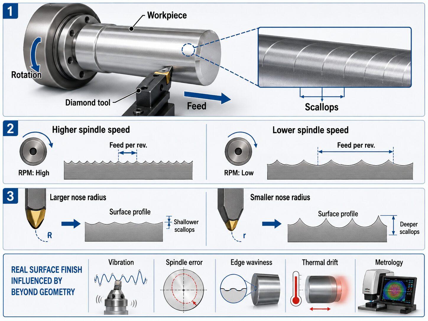
As the workpiece rotates and the cutting tool advances, the tool leaves a repeating geometric pattern on the surface. The spacing of this pattern is related to the distance the tool advances during each spindle revolution, often referred to as feed per revolution. When feed is programmed as distance per minute, spindle speed affects the actual feed per revolution. If spindle speed increases while the programmed feed rate remains unchanged, the tool advances a shorter distance during each revolution. If spindle speed decreases, the tool advances farther during each revolution.
Tool nose radius also influences the shape and height of the resulting feed marks, often called scallops. For the same feed per revolution, a larger nose radius generally produces shallower geometric scallops, while a smaller radius produces more pronounced scallops. Reducing feed per revolution can therefore improve the theoretical surface finish, although doing so also increases machining time.
The actual surface is not determined by geometric scallop height alone. Spindle error, vibration, cutting-edge waviness, material fracture, thermal movement, servo performance, and other process disturbances can create additional texture. A parameter combination that predicts a very small scallop height must still be verified by surface metrology.

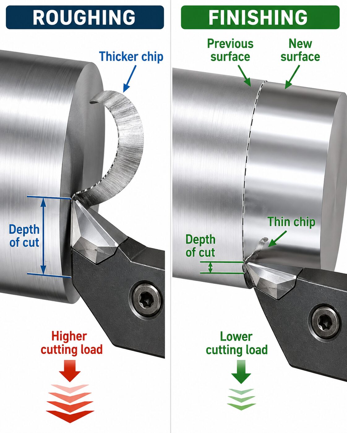
Depth of cut determines how much material the diamond tool removes during a single pass. Roughing operations normally use larger depths of cut so that excess material can be removed efficiently, while finishing operations use much smaller depths of cut to reduce cutting forces and generate the final surface.
Increasing depth of cut generally increases the amount of material being removed and the load placed on the cutting edge. Excessive cutting load can make the process more sensitive to tool condition, workholding stability, machine stiffness, vibration, and material behavior. This is especially important in ultra-precision machining because very small disturbances can become measurable errors on the finished surface.
A finishing cut should be deep enough to remove the surface produced by the previous operation and generate a continuous new surface, but it should not remove more material than necessary. The correct finishing depth depends on the workpiece material, remaining stock, tool geometry, part shape, and capabilities of the machine.
SPDT programs often use a sequence of rough, medium, and finish passes to gradually bring the workpiece to its final geometry and surface condition.
A rough pass is primarily intended to establish the general geometry and remove excess material efficiently. Surface finish is less important during this stage because additional material will be removed later.
A medium pass, when required, reduces the remaining form error and prepares the workpiece for the final cut. It typically uses a smaller depth of cut and may use a more conservative feed than the roughing operation.
The finish pass generates the final optical surface. It normally uses a small depth of cut and a feed rate selected to balance surface quality with machining time. Extremely low feeds can reduce theoretical scallop height, but they also increase the amount of time required to complete the surface.
Not every part requires the same number of passes. The appropriate sequence depends on the amount of remaining stock, surface sag, material behavior, required form accuracy, previous machining operations, and the amount of cutting load that can safely be applied.
Different materials require different cutting conditions because they do not respond to a diamond tool in the same way. Material hardness, ductility, brittleness, thermal conductivity, fracture behavior, and chemical interaction with the tool can all influence the appropriate spindle speed, feed rate, depth of cut, and rake angle. Ductile nonferrous metals such as aluminum, copper, and brass are commonly machined using cutting geometries designed to promote smooth plastic deformation of the material. Brittle optical and semiconductor materials such as germanium, silicon, zinc selenide, and zinc sulfide may require more negative rake angles and carefully controlled cutting conditions to encourage ductile-regime machining and reduce the risk of fracture.
Polymers such as acrylic behave differently from both metals and brittle crystals. Their lower stiffness and sensitivity to heat mean that cutting parameters must account for deformation, temperature buildup, and chip formation. For production work, cutting conditions should begin with a proven or qualified process for the specific combination of material, machine, tool, and part geometry. Adjustments should be made in a controlled manner so that the effect of each change can be evaluated.
SPDT operations may use oil, a light oil mist, liquid coolant, air, or other controlled cutting environments depending on the material and machining process. These fluids and gases can help remove chips, control temperature, reduce friction, prevent debris from accumulating near the cutting edge, and maintain a clean cutting zone. The appropriate method depends on both the workpiece material and the machine. Some materials perform well with a continuous fluid or oil supply, while others may use a light mist or carefully directed air. The cutting environment must also be compatible with the machine components, workholding system, tool, and required surface quality.
Coolant and airflow are also important process-control variables. Changes in flow rate, fluid temperature, spray direction, or mist conditions can alter the thermal and mechanical environment at the cutting edge. During finish machining, the objective is to maintain a stable and repeatable cutting condition throughout the entire pass. Consistent parameters, tool geometry, temperature, and coolant conditions help ensure that differences between parts are caused by controlled machining decisions rather than uncontrolled changes in the process.
This activity shows how spindle speed, feed rate, tool nose radius, and depth of cut work together during diamond turning. Adjust the controls to see how they affect feed per revolution, theoretical scallop height, cutting load, and machining time, and compare how rough, medium, and finish passes use different parameter combinations. The material and cutting-environment selections also demonstrate why SPDT settings must be matched to the workpiece material, operation, and process conditions rather than using one set of parameters for every job.
Change the cutting parameters and watch how feed per revolution, theoretical scallop height, cutting load, and machining time respond.