Setup
Create a stable and known starting condition before the diamond enters the workpiece.
Why it matters

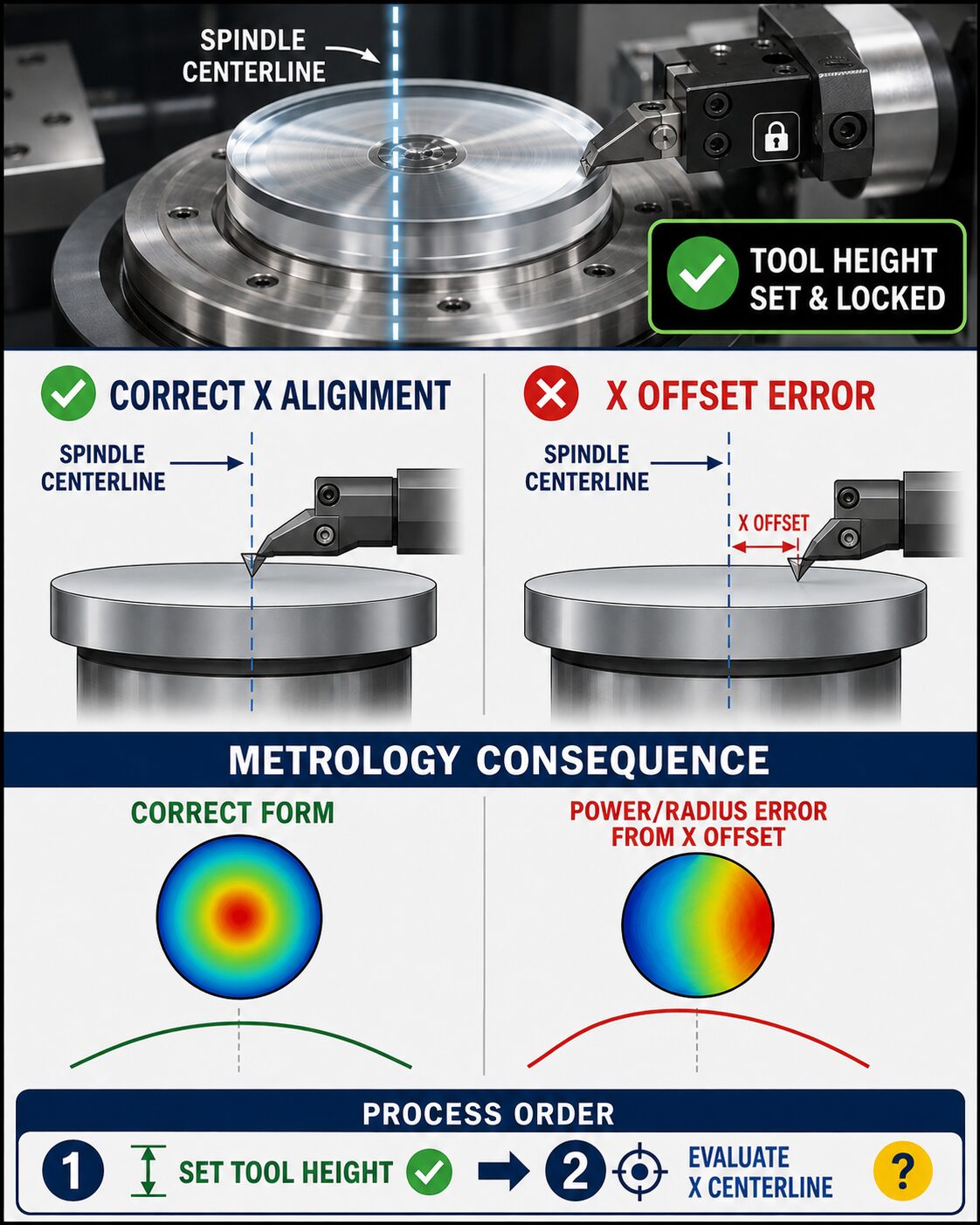 X Offset and Spindle Centerline
After tool-height error has been corrected, the next major geometric question is whether the diamond tool is positioned correctly in X relative to the spindle axis. The X position determines the radial relationship between the programmed tool path and the true center of rotation. If the X offset is incorrect, the tool may not pass through the intended radial position even though the CNC program itself is mathematically correct. This can change the generated radius and may appear in metrology as a low-order form or power error. Tool height should therefore be corrected before X-centerline adjustment begins. Tool-height error and X-offset error can both influence the center region of the surface, but they have different physical causes and require different corrections. Separating them allows the operator to connect each measured change to a specific machine adjustment rather than compensating one error with another.
Before metrology is used to calculate an X correction, the measurement system itself must be properly referenced. An onboard metrology system may use a calibrated reference artifact, such as a precision sphere, installed in a repeatable kinematic fixture. The artifact is aligned to the spindle axis while the spindle rotates, and its runout is reduced to the required level before measurements are accepted. This step is important because an off-center calibration artifact can create an apparent X error even when the tool position is correct. Precision measurement only provides useful machining information when the reference used to make that measurement is reliable. The general rule is straightforward: reference the measurement system before using it to correct the machining system.
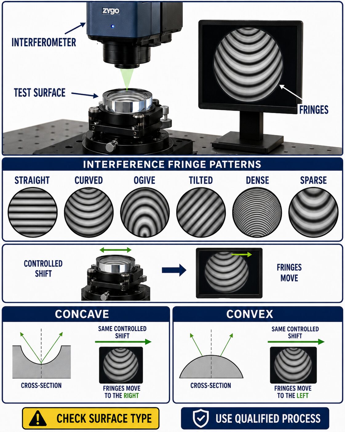 Using Interferometer Fringes
Interferometry can help determine both the magnitude and direction of an X-centerline or radius-related error. When an optical surface does not match the intended geometry, the interferogram may show a curved or ogive-like fringe pattern. The number, spacing, and shape of the fringes provide information about how the measured surface differs from the reference wavefront. Determining the direction of an X correction, however, requires more than simply looking at the static fringe pattern. A small, controlled movement of the test surface relative to the interferometer can be introduced, and the resulting fringe motion can then be observed. That response, together with knowledge of whether the surface is concave or convex, helps determine the sign of the required correction. The interpretation reverses between concave and convex geometry, so fringe motion should never be interpreted without considering the surface type and the direction of the controlled movement. Exact calculations, fringe-count relationships, sign conventions, and allowable corrections should follow the qualified metrology process for the specific machine and optical surface.
Power is a low-order form error associated with the overall curvature of an optical surface. A surface with the wrong power may be slightly too steep or too shallow compared with the intended radius, but that does not automatically mean the programmed radius should be changed. A similar measured result can be caused by an incorrect X-centerline position, an incorrect tool nose radius, an incorrect work offset, workholding or alignment error, a poor metrology reference, or even the wrong CNC program or surface definition. Because X position influences the radial relationship between the tool and spindle axis, X-centerline error and power error can be closely related. Before applying a programmed radius or power correction, the operator should verify the basic setup conditions first: tool height, tool geometry, work offset, X centerline, workholding, metrology reference, and active program. This prevents a software or program change from masking a mechanical setup error that should have been corrected directly.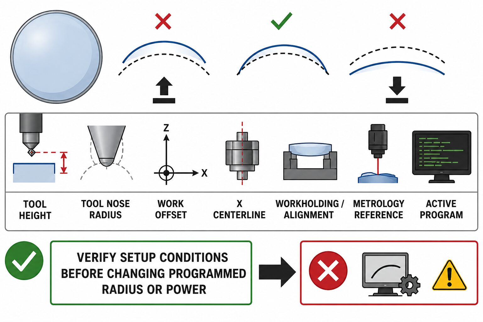
Different SPDT errors have different diagnostic signatures, and recognizing those signatures is an important part of process control. Tool-height error is evaluated primarily from the geometry of the residual center feature. For the applicable zero-rake tool geometry, a conical or cylindrical center feature can indicate whether the cutting edge is above or below spindle centerline. X-offset error concerns the radial position of the tool relative to the spindle axis and, once tool height is correct, may appear as a radius or form discrepancy. Power error describes a broader curvature difference across the optical aperture. These conditions can occur together, but changing several corrections at the same time makes the result difficult to interpret. A more reliable approach is to measure the surface, identify the error with the clearest physical signature, change one variable, recut the part, and measure again. Only after the effect of that correction is understood should the next variable be adjusted.
A controlled single-point diamond turning process begins well before the first machining pass. The machine and environment must be stable, the workpiece material and diamond tool must be appropriate for the operation, mounting surfaces must be clean, workholding must be secure, spindle runout and imbalance must be acceptable, and tool geometry and offsets must be verified. The operator then establishes the correct work coordinate system, confirms the CNC program and cutting parameters, and performs a controlled first cut. The resulting surface is measured rather than judged by appearance alone. Metrology then drives the correction process: center-feature geometry provides information about tool height, interferometric form and radius measurements provide information about X centerline and power, and surface texture can reveal problems involving feed, spindle speed, vibration, tool condition, material response, or process stability. Each correction should have a specific physical reason, be recorded, be applied in a controlled way, and then be verified through another cut-and-measure cycle.
The goal of SPDT is not simply to produce one part that happens to meet specification. A mature process should be repeatable, understandable, and traceable. The operator should be able to explain what error was measured, which variable was changed, why that variable was selected, how much it was changed, and whether the resulting surface moved in the expected direction. This creates a clear relationship between machine setup, cutting conditions, metrology, correction, and final optical performance. The recurring control sequence is:
Measure → Interpret → Correct One Variable → Recut → Measure Again.
Following that sequence reduces guesswork, prevents one error from being hidden by another correction, and makes it possible to return the machine to a known controlled state for the next part. That disciplined feedback loop is what allows single-point diamond turning to function as an ultra-precision optical manufacturing process rather than simply a very accurate form of turning.