
 Evaluating the First Surface
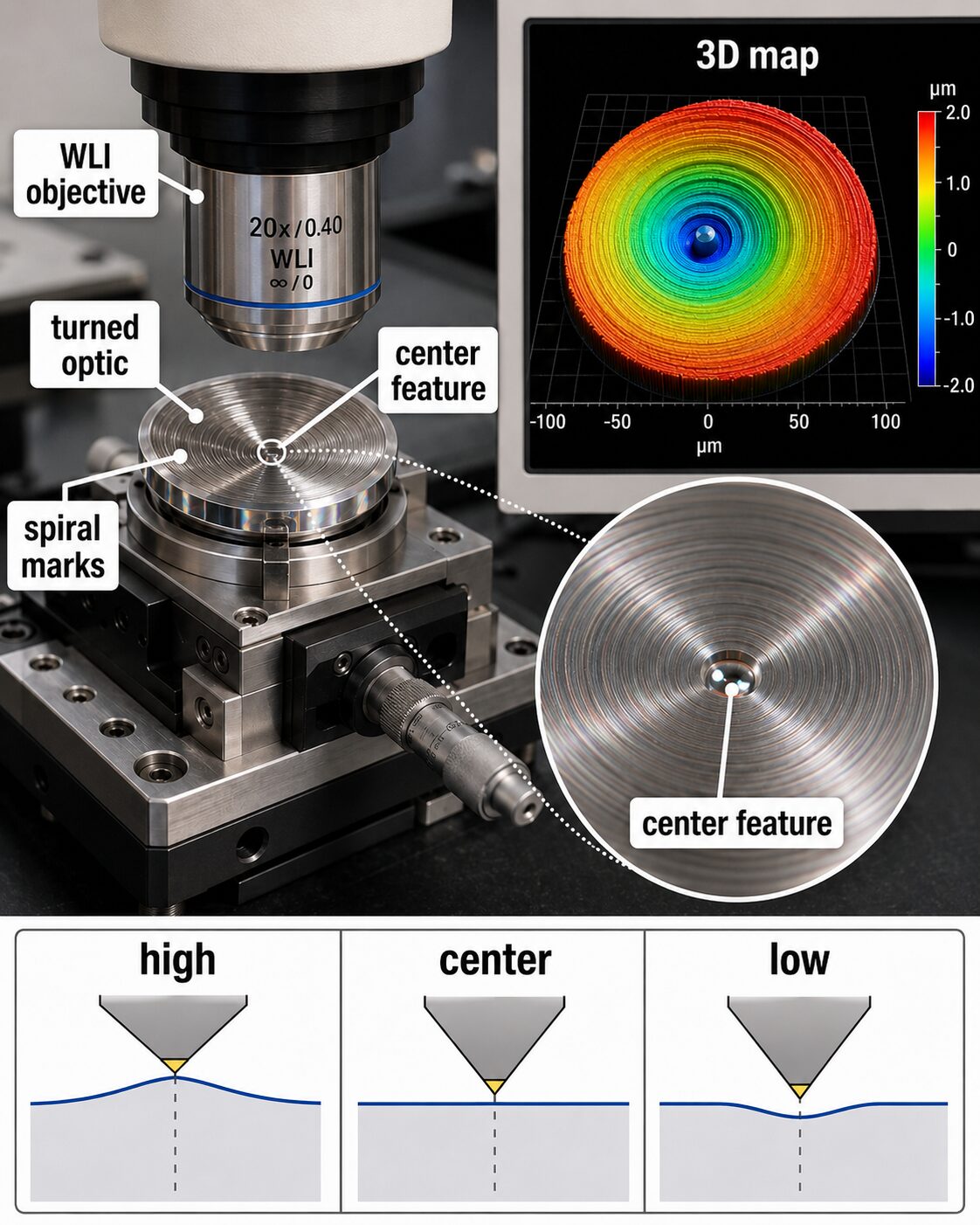
For the zero-rake diagnostic convention used in this lesson, the sloped conical feature indicates that the diamond cutting edge is above the spindle centerline.
In SPDT, the rotating optic and feeding diamond tool generate a spiral path. As the tool moves inward, those marks converge toward the spindle axis.
The WLI-style color map represents relative surface height. Warm colors indicate higher areas and cool colors lower areas; the exact colors themselves are not material properties.
A sloped peak is easier to recognize in the height profile than in a simple microscope image. That geometry is what makes the center feature diagnostic.
As radius approaches zero, tangential cutting speed also approaches zero. That makes the final approach to center especially sensitive to tool height, tool geometry, and exact alignment.
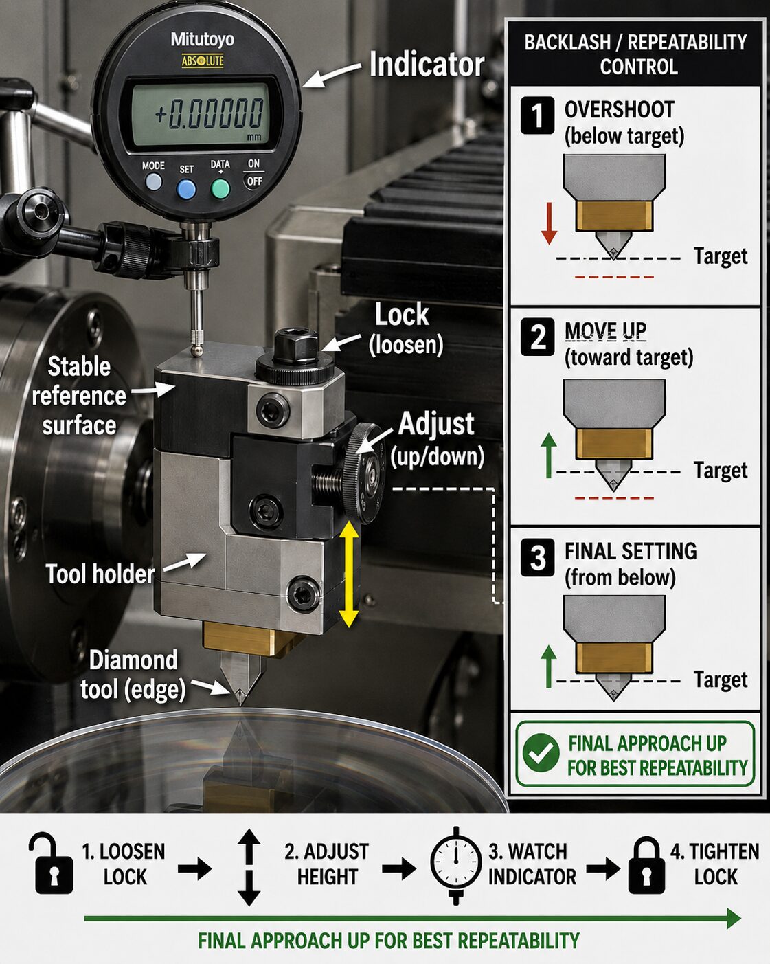 Tool height is commonly adjusted mechanically at the tool holder. A high-resolution indicator can be placed on a stable, noncutting surface of the tool or holder so that the amount of vertical movement can be measured directly. Before adjustment, the tool-height locking mechanism is loosened carefully while the indicator is observed. The adjustment screw is then used to raise or lower the tool by a controlled amount. Backlash in the adjustment mechanism can affect repeatability. For this reason, the final tool position should be approached from the same direction each time. A common method is to make the final approach by moving the tool upward. If the adjustment overshoots the target and the tool must be moved downward, move it below the desired position and then bring it upward again to the final setting. This reduces the influence of thread clearance and makes the adjustment more repeatable.
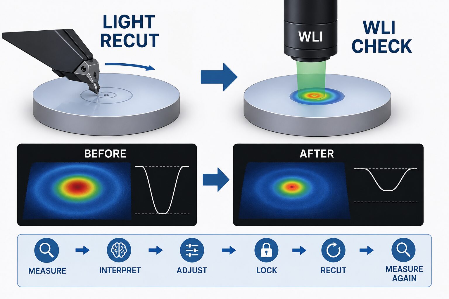 After the tool-height adjustment, the workpiece is recut under controlled conditions. If the workpiece was removed and remounted, the work offset and surface reference should be verified before machining resumes. A rough or semi-finish pass may be used first to re-establish a reliable surface, followed by a light finish pass. The center region is then measured again with WLI. Compare the new center feature with the previous measurement. If the feature becomes smaller and its geometry moves in the expected direction, the correction was effective. If necessary, another small tool-height adjustment can be made. The acceptable center-feature size depends on the part requirements and the qualified machining process. The important principle is the correction sequence: