
By the end of this lesson, you will be able to:
In deterministic polishing, every machining decision is driven by accurate measurement data. Before any material is removed, the optical surface must first be measured to determine exactly how closely it matches the intended design. This measurement establishes the starting point for every polishing cycle and provides the information needed to calculate precise material removal.
Unlike conventional polishing, which often relies on operator experience and repeated trial-and-error adjustments, deterministic polishing uses measured data to make objective, repeatable corrections. Every polishing program is based on the actual condition of the optic rather than an estimate, allowing manufacturers to achieve significantly higher levels of precision and consistency. Without accurate metrology, the polishing machine has no reliable way of determining where corrections are needed or how much material should be removed. Even the most advanced CNC polishing system cannot consistently produce high-quality optics if the measurement data is inaccurate or incomplete. Poor measurements can lead to over-polishing, under-polishing, or introducing new surface errors that require additional correction. Metrology provides the foundation for the entire deterministic polishing process because it supplies the detailed surface information needed to create polishing programs that remove only the required amount of material, exactly where it is needed.
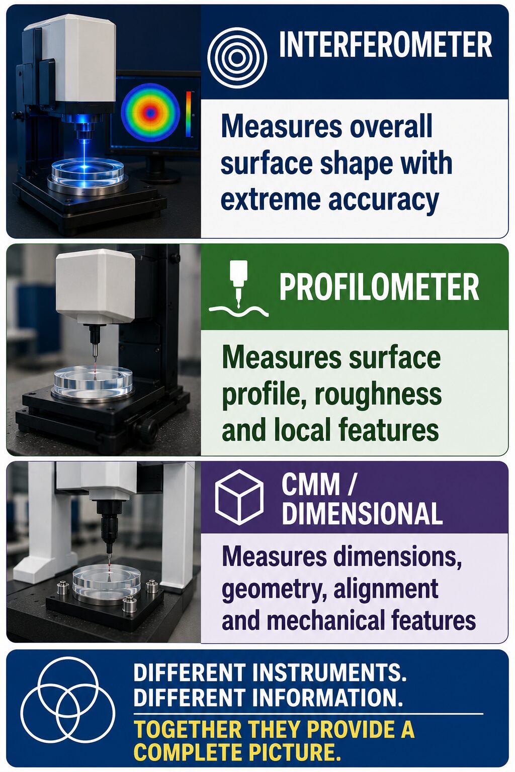
Several different measurement instruments are used throughout optical manufacturing, and each provides unique information about the optic. Manufacturers often combine data from multiple instruments because no single system can measure every characteristic of an optical component.
Interferometers are among the most important instruments used during deterministic polishing. They measure the overall shape of an optical surface with extremely high accuracy by comparing reflected light waves. Because they can detect errors measured in fractions of a wavelength of light, interferometers are commonly used during final polishing when extremely tight tolerances must be achieved.
Profilometers measure the surface profile by scanning across the optic. Depending on the instrument design, they may use either a precision contact stylus or a non-contact optical sensor to collect data. Profilometers are particularly useful for measuring local surface features, step heights, roughness, and complex surface contours that may not be easily evaluated using interferometry alone.
Coordinate Measuring Machines (CMMs) and other precision dimensional inspection systems are frequently used to verify part geometry, alignment, thickness, edge dimensions, and mechanical features. These systems ensure that the optic not only meets optical specifications but also satisfies the dimensional requirements needed for proper assembly into larger optical systems.
Each measurement system contributes different information about the optic, and together they provide a complete picture of the component’s condition throughout the manufacturing process.
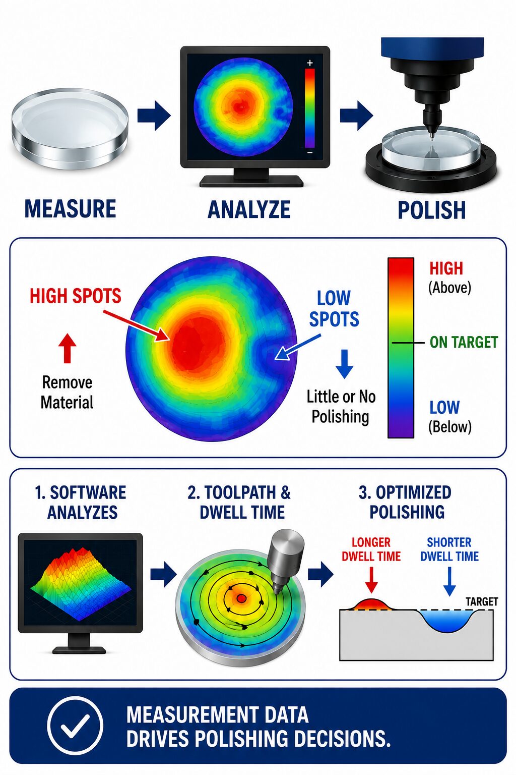
After an optic has been measured, specialized metrology software compares the measured surface to the ideal optical design. The differences between the actual surface and the desired surface are calculated at thousands, or even millions, of individual measurement points. These differences are displayed as an error map, which uses a color scale to represent areas that are either above or below the target surface. Warm colors often indicate material that is higher than desired, while cooler colors represent areas that are lower than the target. The exact color scheme may vary depending on the software, but the purpose remains the same: to provide a clear visual representation of surface errors.
High spots generally require additional polishing because excess material must be removed to bring those areas into specification. Low spots, however, usually receive little or no polishing since material cannot be added back to the optic. Instead, surrounding high areas are gradually reduced until the entire surface reaches the desired profile. The polishing software analyzes the error map and calculates an optimized polishing toolpath. It determines not only where the polishing tool should travel, but also how long it should remain at each location, a concept known as dwell time. Areas requiring greater material removal receive longer dwell times, while areas closer to specification receive less polishing. Learning to interpret an error map is an important skill for technicians because it allows them to understand how measurement data directly influences polishing decisions and machine programming.
Deterministic polishing is an iterative process, meaning that the final optical surface is achieved through a series of carefully controlled correction cycles rather than a single polishing operation. Each cycle begins by measuring the optic to determine its current surface condition. The metrology software analyzes the measurement data and generates a polishing program that calculates the required material removal across the entire surface. The CNC polishing machine then performs the correction using precisely controlled tool motion and dwell times.
After polishing is complete, the optic is cleaned and measured again. The new measurement is compared to the previous results to determine how effectively the polishing operation corrected the surface errors. Because each polishing pass slightly changes the optic, new measurements are always required before the next correction program can be generated. This measure-polish-measure cycle continues until the optic satisfies all required optical specifications. With each iteration, the remaining surface errors become smaller, allowing the polishing process to converge toward the desired surface with remarkable accuracy. The continuous feedback provided by metrology is what makes deterministic polishing predictable, repeatable, and capable of producing today’s highest-performance optical components.
The Error Map Explorer allows you to interact with a sample interferometry map and observe how different polishing strategies affect the predicted optical surface. As you select various correction methods, the software simulates how the polishing tool removes material from different regions of the optic. With each simulated polishing pass, the surface gradually approaches the desired shape, and the error map changes to reflect the improvements.
This activity demonstrates how measurement data directly controls every deterministic polishing operation and illustrates why accurate metrology is essential for successful process control. By experimenting with different strategies, you can better understand how technicians use measurement information to make informed polishing decisions.
Use interferometry data to test correction strategies and watch the predicted surface improve.