
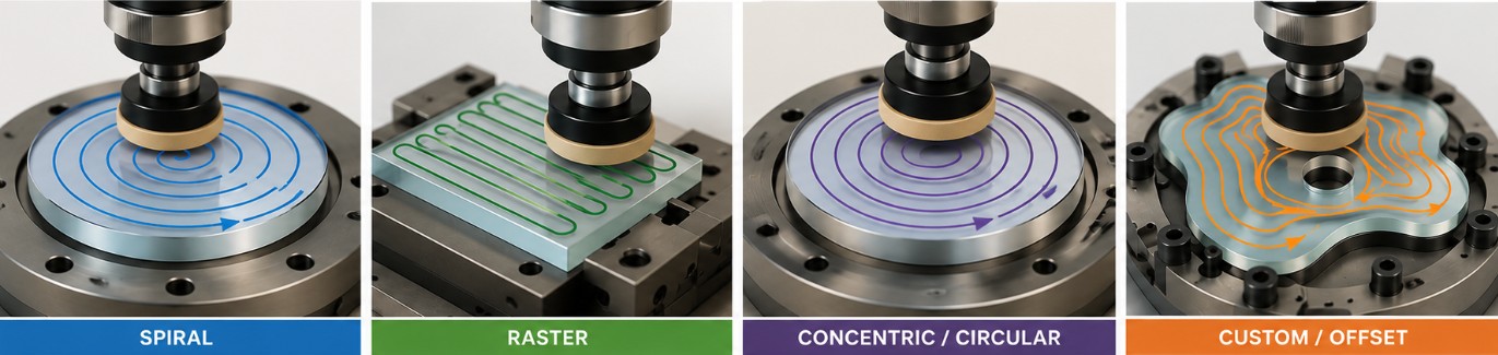
A toolpath is the route the polishing tool follows as it moves across the optical surface. Instead of moving randomly, the CNC machine follows a carefully calculated path that places the tool exactly where material must be removed. The toolpath is created by software using information from the measured surface error and the known removal function of the polishing tool. The surface error map identifies areas that are too high, while the removal function predicts how much material the tool can remove under specific operating conditions. The software combines this information to determine where the tool should travel, how quickly it should move, and how long it should remain in each region. The goal is to remove high areas without disturbing portions of the surface that are already within tolerance. Well-designed toolpaths improve polishing accuracy, reduce unnecessary motion, and help shorten the total manufacturing cycle.
Different optical shapes require different polishing strategies. The selected path must provide complete surface coverage while avoiding repeated marks or uneven removal. Spiral toolpaths are commonly used for rotationally symmetric optics, such as spherical or aspheric lenses. The tool gradually moves from the center toward the edge, or from the edge toward the center, while the optic or tool rotates. This creates smooth and even coverage across a circular surface. Raster patterns move the polishing tool back and forth in a series of straight, parallel lines. At the end of each pass, the tool changes direction and begins another pass. Raster paths are often used for rectangular, cylindrical, and freeform components. Some systems use circular, concentric, or offset paths. Other applications require custom toolpaths designed specifically for the geometry being manufactured. These specialized paths can avoid holes, edges, mounting features, or areas that should not be polished. The best toolpath depends on the optic’s shape, the machine configuration, the polishing-tool size, and the location of the measured surface errors.

As the polishing tool follows its programmed route, the machine continuously adjusts its speed. This changes the amount of time the tool spends over each part of the optic. When more material must be removed, the tool slows down and remains in that area longer. This longer dwell time allows the polishing process to remove more material. When little correction is needed, the machine speeds up and moves across the area more quickly. Some regions may receive very little polishing if they are already close to the required shape. The machine does not usually stop completely at each correction point. Instead, it changes speed smoothly while continuing along the programmed path. This produces a gradual change in removal rather than a series of isolated polished spots. Dwell-time control allows the machine to correct surface errors without replacing the polishing tool or constantly changing the polishing pressure.
The distance between neighboring passes is another important part of toolpath design. If the spacing is too large, sections of the surface may receive too little polishing. This can leave visible bands or uncorrected areas between passes. If the spacing is too small, the tool may repeatedly overlap the same regions. Excessive overlap can increase polishing time and may remove more material than intended. The software normally selects a spacing based on the diameter and shape of the removal function. Each pass overlaps the previous pass enough to create smooth, continuous coverage. Proper overlap helps blend individual tool passes together so that they do not appear as separate marks on the finished optic.
Good polishing depends on smooth and controlled machine motion. Sudden starts, stops, or direction changes can disturb the polishing tool and leave unwanted marks on the optical surface. Rapid acceleration may temporarily change the contact pressure between the tool and the optic. It may also cause vibration, tool deflection, or uneven slurry movement. Each of these effects can change the amount of material being removed. Modern CNC systems use advanced motion-control software to coordinate the machine axes. Acceleration and deceleration are carefully managed so the tool can change speed without producing abrupt movements. Smooth motion is especially important near the center and edge of an optic, where the machine may need to change direction or move through a smaller area. Poorly controlled motion in these regions can create center defects, edge roll, or visible toolpath marks. Properly designed toolpaths improve surface quality, reduce machine wear, and help the polishing process remain repeatable.
Direction changes require special attention during toolpath planning. In a raster path, for example, the tool must slow down at the end of each row before moving in the opposite direction. If the machine changes direction while the tool is still over the optical surface, it may spend too much time near the edge. This can produce excessive removal or edge roll. To avoid this problem, some toolpaths extend slightly beyond the edge of the optic before reversing direction. Other systems adjust speed or pressure as the tool approaches the boundary. The machine software must also prevent the polishing tool from moving so far beyond the optic that it becomes unstable or loses proper contact. Careful edge control allows the tool to polish the full usable aperture without damaging the outside region of the surface.
The machine must place the polishing tool at the correct location throughout the entire path. Even a well-designed dwell program will not work correctly if the machine position is inaccurate. Positioning errors may come from backlash, vibration, thermal growth, worn components, or incorrect machine calibration. Small errors can cause the tool to polish a location beside the area that was intended. High-accuracy encoders and feedback systems continuously monitor the machine axes. The control system compares the commanded position with the actual position and makes corrections when necessary. Regular machine calibration helps ensure that the physical toolpath matches the path calculated by the polishing software.
The Toolpath Visualizer lets you compare spiral, raster, and custom polishing patterns. As the simulation runs, you will see how the tool moves across different regions of the optic. The tool slows down in areas that require greater correction and moves more quickly through areas that need less material removal. You can also observe how path spacing and direction changes affect surface coverage. Compare the patterns and look for areas where the tool passes overlap. Notice how smooth motion creates a continuous removal pattern, while abrupt changes could produce visible defects. Watching these patterns helps explain how machine motion, dwell time, and path design work together to control material removal and final surface accuracy.
See how coordinated workpiece rotation and polishing-head positioning create the relative contact path used in OptiPro-style sub-aperture polishing.
The animation runs for one complete cycle and then stops automatically.