
Curriculum
- 1 Section
- 10 Lessons
- 10 Weeks
- CurriculumThis course is designed for technicians, engineers, and supervisors working in optical fabrication or quality roles or similar precision manufacturing environments. Prior knowledge of basic optics or polishing is helpful but not required.11
- 1.1Lesson 1 – Introduction to CNC Polishing
- 1.2Lesson 2 – Polyurethane & Nylon Pads
- 1.3Lesson 3 – Supporting tool materials
- 1.4Lesson 4 – Zernike Terms Figure Error Interpretation
- 1.5Lesson 5 – Form Error Identification & Correction
- 1.6Lesson 6 – Surface Roughness & Subsurface Damage
- 1.7Lesson 7 – Slurry Fundamentals (Type, APS, Shape, Distribution)
- 1.8Lesson 8 – Diamond Slurry Types (Mono-, Poly-, and Natural)
- 1.9Lesson 9 – Slurry Control, Chemistry & Suspension
- 1.10Lesson 10 – Integrated Process & Practical Insights
- 1.11CNC Polishing in Precision Optics Manufacturing – Final Quiz120 Minutes20 Questions
Lesson 5 – Form Error Identification & Correction
What You Will Learn
- Recognize center peak vs. center hole and prescribe corrections
- Differentiate edge roll from up edge and adjust dwell/pressure
- Identify astigmatism vs. higher-order astigmatism
- Tie each signature to actionable machine and process levers
- Document changes and close the loop with metrology
Understanding Form Signatures
Form errors are not random; they are indicators of how material is being removed across the optic. The goal is not just to recognize the shape, but to understand the cause of the error. Evaluating the surface with only a 2D view highlights symmetrical error, such as center vs. edge error and magnitude of deviation. A 3D view reveals compounded slope surfaces and asymmetric error. Always evaluate the 3D surface map to fully understand the results of the process. A critical first step is separating process-induced error from metrology artifacts. Mechanical misalignment, dirty surfaces, vibration, thermal induced error, stress induced error or biased test plates can produce signatures that mimic real process issues. Confirm repeatability before making corrections.
Center Behavior: Peak vs. Hole
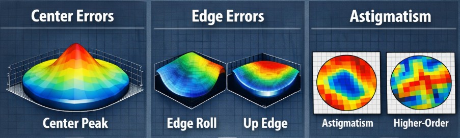
A center peak indicates insufficient material removal at the optic center relative to the surrounding area. This is commonly driven by low dwell time at center, part stress, or tool path bias that favors outer zones. In contrast, a center hole reflects excessive removal at the center, often caused dwell, localized pressure, or tool kinematics that concentrate energy near the center. Corrections should focus on redistributing removal rather than making large global adjustments. Check tool conformity, if the lap is not making uniform contact, center features will persist if pressure distribution is not consistent from center to edge. Center features can also be the result of radius change or correction.
Edge Behavior: Roll edge vs. Up Edge (Spherical Aberrations – SA3)
Edge roll is characterized by excess material removal near the outer edge of the optic, resulting in a turned-down edge.
There are a number of factors that can be cause edge roll:
- insufficient mechanical support of the optic (evaluate lens geometry, thin edge optics or thin center optics can flex during polishing processes as a result of the polisher and bladder pressure)
- Polisher shape mismatch, too much material removal at the edge
- excess contact pressure by the polishing tool on the edge of the optic,
- change in radius of curvature
- number of oscillations per minute of the polisher across the surface of the optic resulting in too much dwell time of the polisher at the edge.
- Increased lens RPM can also cause edge roll as a result of higher surface velocity at the edge of the optic resulting in more material removal.
Inversely up edge conditions can be caused by the some of the following issues
- insufficient material removal at the edge of the optic
- insufficient oscillation length across the optic leaving the edge “stranded” due to path limitations.
- polisher shape mismatch, too much material removal in the center of the optic.
- insufficient pressure at the edge, increased pressure concentration in the center
- Change in radius of curvature
Correcting edge conditions requires careful balance and understanding of the lens geometry and pressure being applied.
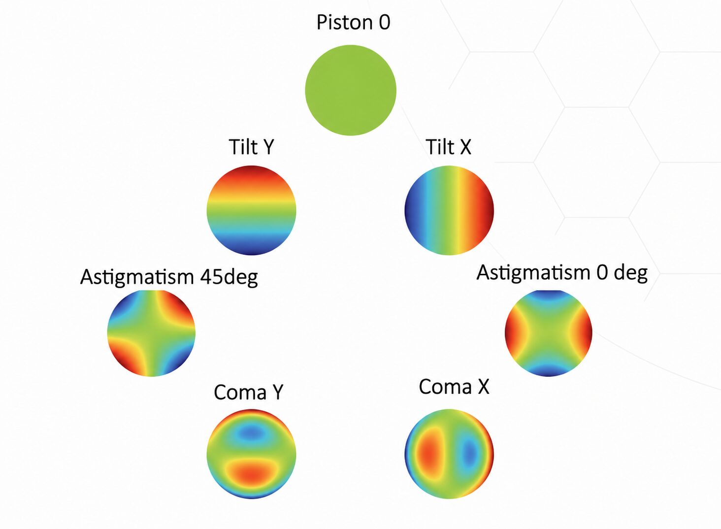 Low and Higher-Order Terms
Low order errors are considered to be Zernike terms are at the top of the pyramid. These are directional errors and are a clear indicator of non-axisymmetric process behavior. Common causes include uneven fixturing, tool tilt, machine misalignment, or periodic frequency timing between part rotation and oscillation.
Higher order errors introduce more complex multi-lobed structures, often tied to dynamic instabilities or compound misalignments or machine harmonics. Unlike symmetric errors, these cannot be corrected purely with radial dwell adjustments. Instead, investigate mechanical alignment first. Verify that the optic is supported evenly, the tools are running true, and motion axes are desynchronized. Small angular misalignments can produce large astigmatic signatures. Process adjustments may include rebalancing relative speeds, correcting tool tilt, or modifying path strategies to eliminate directional bias. If higher-order terms persist, evaluate machine alignment tool harmonics and vibration sources.
Linking Form Error to Process Influences
Each form error can sometimes map directly to a controllable variable. Pressure distribution governs where removal occurs. Pressure determines how strongly the tool engages the surface. Relative velocity controls removal rate and interaction uniformity. Thermal conditions influence material response. Tool 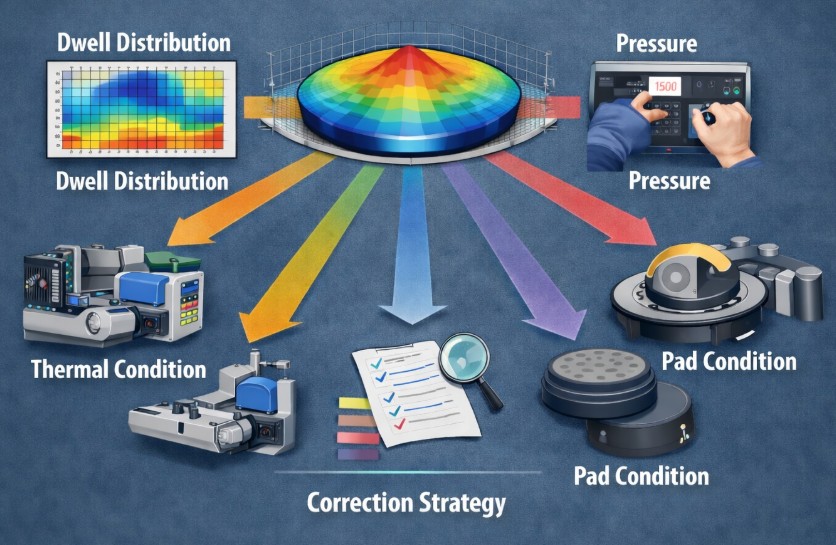 compliance and pad condition affects how consistently energy is transferred. Form error correction comes from adjusting one variable at a time while. Isolating the changes and evaluating cause and effect, making it easier to converge on the correct solution. Large simultaneous changes often mask the true driver and slow down convergence.
Correction Strategy
Approach corrections incrementally. Start with the dominant error term and reduce its magnitude before addressing secondary features. Ultimately maintain control of radius of curvature. Drastic changes in radius will contribute to form error in polishing. Use small, controlled adjustments to dwell or pressure rather than sweeping changes. Monitor how the error evolves- directional improvement is more important than immediate perfection. Always consider compound interactions. For example, changing edge dwell to fix roll may introduce power change. Correcting one issue may present others. Corrections should move the surface toward a more uniform removal profile without introducing new asymmetries.
Verification and Closed-Loop Control
After implementing changes, reacquire metrology using consistent setup conditions. Compare both visual maps and quantitative Zernike coefficients. The objective is to confirm that the correction moved the error in the intended direction and reduced its magnitude. Trend analysis is critical. A single measurement confirms direction, but multiple iterations confirm stability. If the response is inconsistent, revisit assumptions about metrology, tool condition, or environmental factors. Maintain a detailed change log for each run, including dwell adjustments, pressure settings, tool condition, and environmental notes. Over time, this builds a process knowledge base that allows faster troubleshooting and more predictable outcomes on future jobs. When the process is refined and running smoothly, document all factors of the process, tooling, environment, material, metrology.
A disciplined, closed-loop approach- measure, adjust, verify- is what transforms form correction from trial-and-error into a controlled, repeatable process.