
What You Will Learn
- Choosing the correct transmission sphere
- Avoiding collisions in CX testing
- Alignment for accurate results
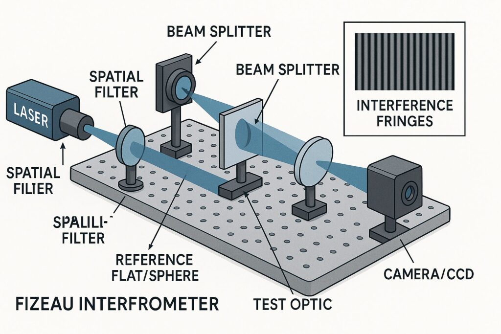 Interferometers are instruments that measure how smooth and accurate an optical surface is by using light waves. They compare the light reflected from a “reference” surface, something we trust to be very accurate, to the light reflected from the surface we are testing. The pattern made by the overlapping waves is called an interference pattern, and it tells us if the test surface is flat, too curved, or has tiny bumps and valleys. A transmission sphere (for testing curved surfaces) or a transmission flat (for testing flat surfaces) acts like the high-precision ruler in this setup. It shapes the interferometer’s beam so that it matches what the test surface should look like if it were perfect. When the test surface is exactly the right shape, the light comes back as expected and the interference pattern looks simple and straight. When it isn’t, the pattern bends, twists, or shows rings that we can measure.
F-Number (F/#): What It Means and Why It Matters
![]() The F-number on a transmission sphere tells you how “fast” or “slow” its beam is, which is another way of saying how strongly it bends light. A fast sphere (small F/# like F/1.5 or F/2) bends light a lot and matches surfaces with short radii of curvature, these are “steeper” curves. A slow sphere (larger F/# like F/7 or F/10) bends light only a little and matches long radii of curvature, these are “gentler” curves.
The F-number on a transmission sphere tells you how “fast” or “slow” its beam is, which is another way of saying how strongly it bends light. A fast sphere (small F/# like F/1.5 or F/2) bends light a lot and matches surfaces with short radii of curvature, these are “steeper” curves. A slow sphere (larger F/# like F/7 or F/10) bends light only a little and matches long radii of curvature, these are “gentler” curves.
Think of it like trying on shoes. If your foot is very curved (short radius), you need a shoe that curves more (fast sphere). If your foot is barely curved (long radius), you need a shoe that curves less (slow sphere). When the F/# matches the lens’s design, the interferometer sends the right wavefront to the test surface and gets a clean, meaningful pattern back.
If you pick a sphere that’s too fast for a long-radius lens, the beam won’t match well and the pattern can look warped or crowded with fringes that don’t make sense. If you pick a sphere that’s too slow for a short-radius lens, the beam under-bends and again you get hard-to-interpret results. Start by estimating the radius of curvature of the lens and choose the F/# that was designed to cover that radius. Many labs keep a chart that lists which transmission sphere goes with which radius range.
Avoiding Collisions in Convex (CX) Testing
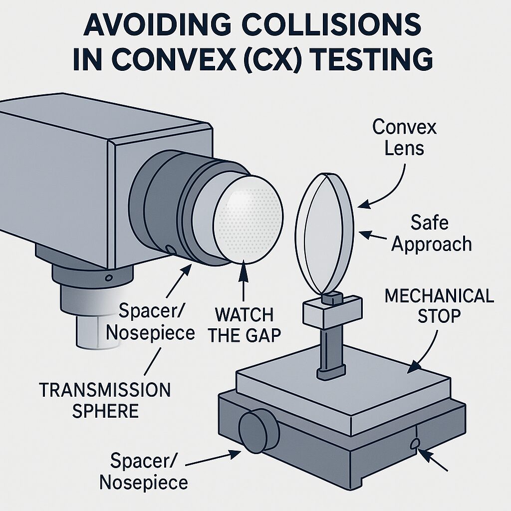 Testing convex surfaces is where you must be extra careful. A convex lens bulges outward toward the instrument, and the transmission sphere also protrudes from its mount. If you move the lens in too quickly, the glass can bump the metal housing or the front of the sphere. That risks chipping the optic, scratching the reference, or both.
Move slowly and watch the gap with good lighting. Keep one hand on the stage controls and your eyes on the clearance, not on the computer screen. If your setup has a mechanical stop or a focusing rail with a scale, set a safe limit before you begin. If there’s a protective spacer or nosepiece recommended by the manufacturer for CX testing, install it. Never force contact; you only need to approach the focus position until the fringes come into view.
Alignment for Accurate Results
Alignment is about making sure the reference wave from the transmission sphere and the reflected wave from your lens overlap in the right way. If the optic is tilted or off-center, the fringes will be tilted, curved, or running off the screen, and your measurement will include alignment errors instead of just the lens shape.
Begin by placing the lens so its center is approximately on the beam axis. Use the stage to move the optic forward or backward until you start to see fringes. If the fringes are slanted, gently adjust tilt until they become more horizontal and fewer in number. When the pattern shows only a handful of straight, evenly spaced fringes, you are close to normal incidence, this is the best position to measure shape errors accurately. If your system offers live alignment aids or an auto-alignment hint, use them to fine-tune the position, then take a short sequence of measurements to confirm the results are repeatable.
Transmission Spheres vs. Transmission Flats
A transmission flat is used for testing surfaces that should be flat, such as optical windows or mirrors with no curvature. It delivers a plane wave to the test part. A transmission sphere is used for testing spherical or nearly spherical surfaces. It delivers a spherical wave that matches the curvature the part is supposed to have. Using the wrong one is like using a ruler to measure a curve or a curved template to judge a flat line, you will get misleading results.
Once aligned, look at the interference fringes. Straight, evenly spaced lines usually mean the surface matches the reference well in overall shape. Bending or crowding of fringes suggests higher or lower power (the surface is too strong or too weak in curvature). Twisted or saddle-shaped patterns can indicate astigmatism. Modern interferometer software captures several frames while shifting the phase, then reconstructs a detailed height map and calculates statistics like peak-to-valley (PV) and root-mean-square (RMS) error. The cleaner your alignment and the better your F/# match, the more trustworthy those numbers will be. Used to test surfaces that should be flat (e.g., windows, flat mirrors). Delivers a plane wave to the part. Alignment quality and F/# match affect how trustworthy the numbers are. Used to test spherical or nearly spherical optics. Delivers a spherical wave that matches the target curvature.
Transmission Flat
Transmission Sphere
Common Mistakes and How to Avoid Them
One frequent mistake is choosing a transmission sphere by convenience instead of by the lens’s radius range. This leads to patterns that are hard to interpret and wasted time. Another is rushing the approach in convex testing, which risks damage. A third is stopping alignment as soon as any fringes appear. Taking a few extra moments to straighten and reduce the number of fringes pays off with better, more repeatable measurements. Finally, touching the test surface with bare fingers can add films or heat that distort the result; handle optics by the edges and let them reach room temperature before testing.
Imagine you need to test a small convex lens with a short radius of curvature. You would pick a fast transmission sphere with a small F/# that covers that short radius range. You would mount the lens securely, turn on good lighting, and slowly bring the lens toward focus while watching the physical clearance. As fringes appear, you would gently adjust tilt until the pattern straightens and the number of fringes decreases. You would then capture data and compare the measured power and irregularity to the lens’s specification. If the pattern looked wild and crowded from the start, you would pause and confirm that the sphere’s F/# actually matches the lens’s radius.
Key Terms
Interferometer: An instrument that compares light waves to measure surface shape.
Transmission sphere: A precision optic that creates the curved reference wavefront for testing spherical surfaces.
Transmission flat: A precision optic that creates a flat (plane) wavefront for testing flat surfaces.
F/# (F-number): Describes how strongly the transmission sphere bends light; small numbers are “fast” (short radii), large numbers are “slow” (long radii).
Radius of curvature: How sharply a surface curves; short radius means more curve, long radius means less.
By choosing the right transmission sphere, approaching carefully during convex testing, and taking a little extra time to align, you get trustworthy results without damaging expensive optics.