
Lesson 7- Air Bearing Stations
What You Will Learn
- Measuring wedge (edge-thickness difference, ETD) and mechanical runout
- When and how to use an air bearing for blocking and pre-inspection
- Accuracy requirements, fixtures, and handling to avoid damage
Overview
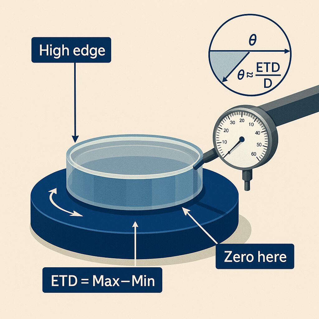
An air bearing station is a flat, ultra-low-friction turntable that floats on a thin film of air. When a lens or mirror is placed on the table and rotated, a mechanical indicator (dial or digital) detects tiny changes in height or thickness with very little friction. This makes it ideal for measuring edge-thickness difference (ETD, “wedge”) and mechanical runout with micron-level precision.
ETD / Wedge: The difference between the thickest and thinnest points at the optic’s edge. If one side is thicker, the faces aren’t parallel—there is a slight wedge angle.
Runout: The peak-to-valley variation of indicator reading as the part rotates; it reflects how much a surface “wobbles” relative to the rotation axis.
Datum: The trusted reference. On an air bearing, the table surface is the datum for height changes; with an indicator at the rim, the edge is the measured feature.
 Equipment You’ll Use
Air bearing turntable with clean, flat top plate; mechanical indicator and rigid stand/arm (1 µm resolution typical, 0.5–1.0 µm common, 0.1 µm for tight work); edge-contact (small-radius, polished ball) or flat-contact tips; soft pads or finger cots; clean, regulated, filtered air supply.
- Clean and warm-soak: Clean the table and the optic. Allow both to reach room temperature to minimize drift.
- Level and air on: Verify the table is level; turn on air and confirm smooth, free rotation.
- Indicator alignment: Mount the indicator so the tip is normal to the measured surface (edge or face).
- Minimize cosine error by keeping the tip’s motion aligned with the indicator’s axis.
- Zero at a known point: With the optic placed gently, choose a reference azimuth and zero the indicator there.
- Light, even support: If you use a center plug, three-point support, or thin paper shims, keep them consistent to avoid tilt.
Measuring Edge-Thickness Difference (Wedge / ETD)
Tip at edge: Position the indicator tip at the outer rim on a consistent land (not on chips or bevels).
Rotate smoothly: Turn the table 360° slowly, noting the maximum and minimum readings.
Record ETD: Subtract the minimum from the maximum. Mark the azimuths if you need to align wedge later for blocking.
Repeatability check: Lift and re-seat the optic; repeat. Consistent ETD within tolerance confirms a good setup.
Small ETD means more parallel faces (low wedge). Larger ETD indicates greater wedge; the azimuth of the maximum reading shows the “high edge.”
Measuring Mechanical Runout (Face or Edge)
Face runout: Lightly place the tip on the optical surface near the outer zone (protect coatings as needed). Rotate 360°. Runout is the peak-to-valley reading.
Edge runout: Place the tip on the cylindrical edge and rotate. Large runout can indicate out-of-round, chips, or poor seating.
Low runout suggests the measured surface is well-aligned to the rotation axis. High runout can come from dirt, tilt, a flexible indicator arm, or a true part condition (warp, bow, or roundness error).
Using Air Bearings for Blocking
Before cement or pitch blocking, use the air bearing to find and mark the high edge from ETD, choose orientation on the block so wedge direction is controlled for downstream operations, and verify centering pre- and post-block by checking runout on a reference surface.
Resolution: Use 1 µm (0.001 mm) or better for most optics; 0.1 µm for tight work.
Cosine error: Keep the indicator tip motion aligned with the measurement axis; even a 10° misalignment introduces about 1.5% error.
Contact force: Use minimal, consistent force to prevent dragging and false readings.
Environment: Maintain stable temperature and avoid drafts; micron readings drift with temperature and air pressure.
Repeat checks: Re-seat the part and re-zero to confirm measurements.
Documentation: Record ETD, runout, tip type, and azimuths to enable traceable alignment and rework decisions.
Handling and Safety
- Clean the table and the optic before contact.
- Do not slide the optic under load—lift, place, and rotate gently.
- Use finger cots or vacuum pencils where appropriate.
- Keep the indicator tip polished and free of burrs; replace worn tips.
Common Issues and Fixes
Readings are jumpy: Clean the table and part; check the air supply and the indicator tip.
Inconsistent ETD: Re-seat the part; ensure the tip is on the same edge land; reduce contact force.
Unexpectedly large runout: Check indicator arm stiffness; inspect for edge chips; verify table level; ensure the part isn’t rocking.
Zero drifts: Allow warm-soak; avoid temperature gradients; re-zero periodically.
Math & Formulas
ETD (Edge-Thickness Difference):
ETD = T_max − T_min
Wedge angle (small-angle approximation, ETD ≪ D):
θ (radians) ≈ ETD / D
Convert to degrees:
θ_deg ≈ (ETD / D) × (180 / π)
Convert to arcminutes:
θ_arcmin ≈ (ETD / D) × 3438
Runout (peak-to-valley):
Runout = R_max − R_min
Example:
For a 100 mm lens with ETD = 15 µm,
θ_arcmin ≈ (0.015 mm / 100 mm) × 3438 ≈ 0.52 arcmin