
Lesson 4- Eye Loupe Inspection
What You Will Learn
- Capabilities of measuring loupes
- Typical uses on the shop floor
- Limits of resolution
Overview
 A measuring eye loupe is a compact magnifier with an internal reticle (scale) that lets you judge small features quickly, hip size, scratch length/width, bevel width, small pits, edge nicks, and debris. It’s ideal for rapid “go/no-go” checks when tolerances are loose (≈ ±0.10 mm) and absolute accuracy isn’t critical. Think of it as a speed tool for visual metrology rather than a replacement for calipers, micrometers, or a measuring microscope.
Anatomy of a Measuring Loupe
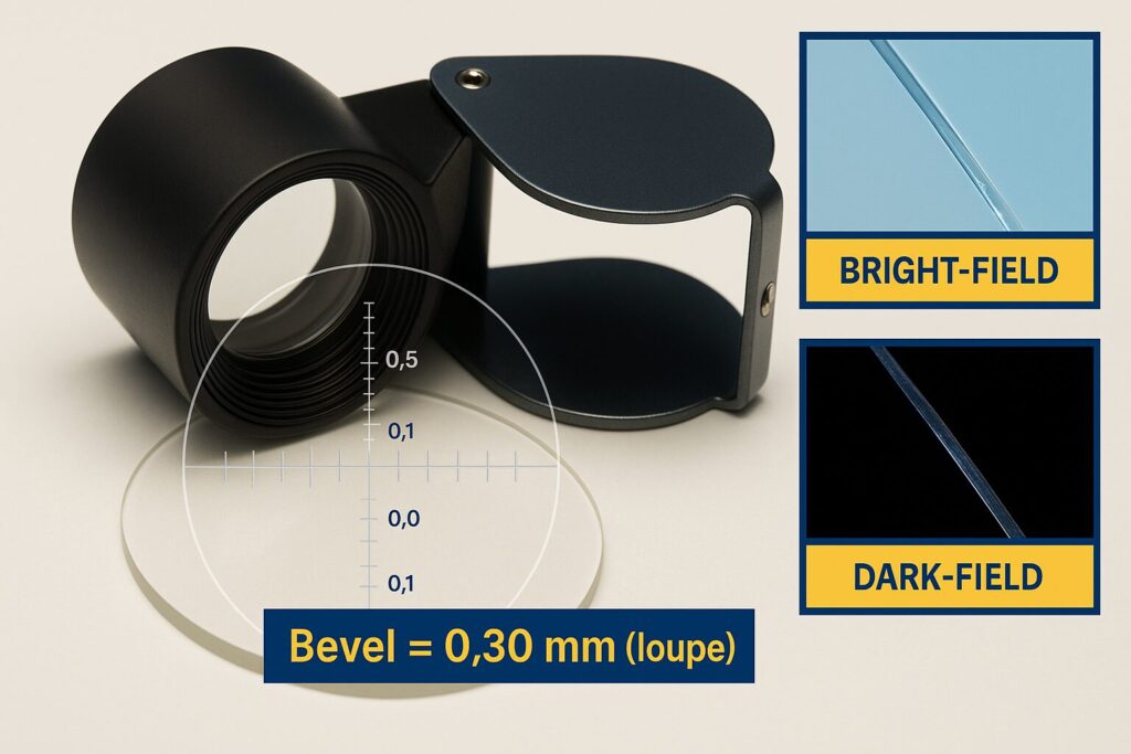
Most shop loupes provide 10×–15× magnification and include a reticle etched in 0.1 mm or 0.05 mm divisions. Some models add a crosshair, protractor marks, or interchangeable reticles. The base is usually skirted so you can stand the loupe square to a surface; higher-end units include adjustable focus and illumination.
Use the loupe at the beveling station to verify bevel width before parts move to cleaning or coating. Use it at inspection to confirm that edge chips are within the allowable zone and that scratch-dig defects are absent from the clear aperture. It also helps when setting up fixtures, verifying that a part is truly seated, that tape or pitch hasn’t crept into the optical zone, and that cleaning removed residue rather than smearing it.
Basic Technique (Fast SOP)
Clean the optic and the loupe’s contact rim first. Place the loupe flat so the reticle plane is parallel to the surface; this reduces parallax and keeps the field in focus. Adjust focus until reticle lines are crisp, then bring the feature into view by sliding the loupe rather than tilting it. When measuring a bevel, align a reticle line with the bevel’s outer edge and read the inner edge against the scale. For a scratch, align the scratch with the scale and read its length; for width, rotate the loupe so the scale is perpendicular to the scratch.
Reading the Reticle and Estimating Size
The loupe doesn’t “increase accuracy” by magnification; it makes the scale easier to read. Your effective resolution is set by the smallest reticle division and how well you can interpolate between marks. With 0.1 mm divisions most operators can reasonably estimate to half a division. That makes ±0.05 mm the practical lower bound, but shop variability and alignment error usually expand total uncertainty toward ±0.10 mm.
Quick example: If the bevel spans 3.2 divisions on a 0.1 mm reticle, report 0.32 mm and round to the nearest 0.05–0.10 mm depending on your procedure.
Measuring Eye Loupe Trainer
Drag the loupe over the cat. When centered, you'll see a green halo/check and the measured diameter.
Sources of Error and How to Reduce Them
Parallax appears when the reticle isn’t parallel to the part. Keep the base flat and your eye centered. Focus error happens when you read before the reticle is tack-sharp, refocus until the etched lines look etched, not fuzzy. Cosine error appears if you’re not measuring perpendicular to the feature; rotate the loupe so the reticle lines are square to the edge or scratch. Lighting error hides faint digs; use bright, grazing light from a penlight and re-check under dark-field when in doubt.
Capability and Limits (Know When to Switch Tools)
Use the loupe confidently for tolerances around ±0.10 mm (bevel width, small chips, quick scratch length). Switch to a micrometer, calipers, or an optical comparator when tolerances are tighter, when you need traceable measurements, or when the feature is sub-0.05 mm. For surface quality grading or acceptance data, a microscope or comparator with calibrated reticles is preferred.
Documentation and Acceptance Calls
Record the feature, the observed value, the reticle division size, and the lighting condition you used (bright-field, dark-field, grazing). Because loupe results are subjective, pairing the numeric estimate with a photo through the loupe or a quick smartphone capture improves repeatability between operators.
Care, Calibration, and Safety
Keep the base rim and lens clean; a dusty rim can scratch optics. Store the loupe in a pouch, not loose in a pocket with tooling. Verify the reticle scale monthly by viewing a certified stage micrometer or a thin steel rule; if the reading drifts, tag and replace the loupe. Avoid leaning your weight onto the loupe over coated or soft surfaces; use a protective film or stand if needed.
Lay out a small training plate with scribed 0.25 mm, 0.50 mm, and 1.00 mm lines and several deliberately sized bevels. Have each operator measure the same features and compare results. If spread exceeds ±0.10 mm for bevel width or ±0.5 mm for scratch length over 10× repeats, retrain on alignment and lighting.
Choose the loupe when you need speed and a rough-order number. Use calipers for fast, traceable dimensions ≥0.5 mm wide where the jaws can reach, micrometers for precision thickness/diameter, and microscopes/comparators for fine edges, micro-chipping, and acceptance-grade defect calls.