
Lesson 3- Basic Hand Tools
What You Will Learn
- Measuring principles of calipers and micrometers
- Precision limits and common pitfalls
- Shop-floor applications
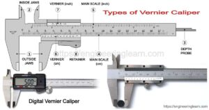
Calipers and micrometers are the day-to-day backbone of dimensional control on the optics floor, but they are not interchangeable. Calipers excel at fast checks on blanks and non-critical dimensions. Their jaws translate distance to a scale (vernier, dial, or digital) and give you quick answers, but the reading is sensitive to jaw pressure, part tilt, burrs, and dirt on the beam. In routine shop conditions, calipers will proved measurements to ±0.01 mm when used correctly. That’s why calipers are appropriate for blank size verification or rough setup, not for ideal for tight tolerances. Calipers are very versatile, they can measure outside diameter and thickness, inside diameter and slot width, they can measure step face width, and they can measure depth.
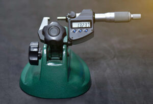
Micrometers trade speed and versatility for precision. The anvil and spindle generate a well-controlled contact geometry, and the ratchet or friction thimble enforces repeatable measuring force. With good technique and a clean part, you can routinely achieve readings to 0.001 mm, and on a well-kept instrument even better. Because the contact line is narrow, alignment matters: any tilt between the micrometer and the part introduces cosine error and false “tight” readings. Roll the part gently between anvil and spindle while you close with the ratchet; feel for the moment of tangency and stop at the first consistent click sequence. If a value drifts as you keep clicking, you’re deflecting the part or the frame—back off and re-seat. There are specialty micrometers for unique applications. Use Micrometer stands to hold the instrument if needed to ensure safety of the optic and the micrometer.
Micrometer Reading Trainer
Goal: learn to read itHow to read it properly
- Sleeve: note the last whole mm visible, plus the half mark if crossed (or 0.025" blocks in inch mode).
- Thimble: read the division at the red index; multiply by 0.01 mm (or 0.001").
- Vernier (optional): add the aligned vernier value: 0.001 mm (or 0.0001").
- Total = Sleeve + Thimble (+ Vernier). Use mouse wheel or drag the knurl. Shift=coarse, Alt=fine.
Before either tool touches a part, set yourself up for success. Wipe the measuring faces with clean tissue, zero the instrument (close the micrometer lightly on a certified standard or to its built-in zero; close calipers fully to confirm zero), and let tools and parts equalize to room temperature. Body heat on a thin lens or a warm instrument can move readings by several microns. Measure at the same point on the part each time—scribe a tiny witness mark on a blank (outside the clear aperture) if needed to ensure repeatability across operators.
Technique can drastically influence the outcome. With calipers, use the flat of the jaws, not the tips, and avoid “peeking” pressure by pushing inward; instead, close to contact and then apply just enough pressure to remove daylight without flexing the jaws. With micrometers, keep the spindle axis aligned to the feature axis. For outer diameters, a standard mic is fine; for wall thickness, a ball-anvil mic avoids edge-reading error; for soft or small parts, use a larger anvil.
Common pitfalls recur and are easy to prevent. Dirt or slurry film on measuring faces reads “big.” Burrs or a tiny rolled edge read “big”. A lens held off square between caliper jaws reads oversize; the same misalignment in a micrometer will read larger than it should. Over-tightening the micrometer induces elastic compression and will provide a smaller than desired measurement. The ratcheted thimble reduces over tightening.
Scale approx: 1 px ≈ 0.02 mm. Reading uses main scale + vernier offset.
Always inspect and calibrate the metrology tool before using it. Verify zero, measure a certified gauge block near your target size, take three readings at 120° apart, and log the mean and spread. If the spread exceeds your process capability, stop and fix technique or tooling before continuing. For parts near the tool’s range limits, choose a different micrometer.
Care and calibration are part of measurement. Store tools clean and closed lightly, never clamped. Keep a small set of gauge blocks at the bench to spot-check before a run. If a tool is dropped, quarantine it until it passes a gauge block test. Schedule periodic calibration for micrometers you rely on for acceptance data, and document those checks in the traveler or calibration log, so your measurements stand up to audit.
Be aware of the metal anvils and edges of the metrology tools. They are sharp and can cause serious scratches and chips to the surfaces of lenses. Approach surfaces to be measured with safe clearance between metal measuring edges and polished surfaces.