
What You Will Learn
- Choose the right transmission sphere by R/# and coverage.
- Predict full-aperture coverage from part geometry.
- Avoid collision risks with mismatched F/# vs radius.
- Interpret how transmission-sphere design and interferometer geometry influence accuracy and repeatability.
- Distinguish between partial, full, and over-coverage setups and know when each is acceptable.
Understanding the Role of Transmission Spheres
![]() Transmission-sphere selection defines the limits of what your interferometer can safely and accurately measure. Each transmission sphere shapes and focuses the test beam, determining how much of the optical surface can be measured without distortion or mechanical interference. Selecting the correct sphere ensures complete coverage of the part’s clear aperture while maintaining a safe working distance between the interferometer and the test surface.
Transmission-sphere selection defines the limits of what your interferometer can safely and accurately measure. Each transmission sphere shapes and focuses the test beam, determining how much of the optical surface can be measured without distortion or mechanical interference. Selecting the correct sphere ensures complete coverage of the part’s clear aperture while maintaining a safe working distance between the interferometer and the test surface.
Matching F/# and R/#
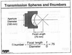
Every transmission sphere has a designated F-number (F/#)- the ratio of its focal length to its aperture diameter. The surface under test, in turn, has a radius of curvature (R/#) derived from its geometry. To achieve proper focus and coverage, the R/# of the surface must be greater than or equal to the F/# of the sphere. If a sphere’s F/# is too fast relative to the surface, the converging beam may intersect the part or housing, risking mechanical collision or measurement distortion. A simple rule of thumb: R/# > F/# ensures safe clearance and accurate illumination.
Determining Coverage and Avoiding Collisions
Begin by defining the clear aperture- the usable optical area of the lens or mirror- and compare it with the projected beam footprint from your selected sphere. “Full coverage” means the entire optical area falls within the interferometer’s test beam. “Partial coverage” can be acceptable if the region of interest is captured and the missing area can be measured through stitching. Always verify that the distance between cat’s-eye and confocal positions equals the surface radius of curvature. This geometric check quickly reveals whether a given transmission sphere will clear the optic or risk collision.
Visualizing and Validating the Setup
Optical modeling tools, such as the Zygo coverage calculator. Sketching the test geometry and labeling each position (cat’s-eye, confocal, vertex) makes it clear where the interferometer’s reference wavefront will interact with the part. If clearances are tight, choose a slower (higher F/#) sphere or reduce the test aperture until a safe margin exists.
Managing Practical Coverage Tradeoffs
In real production environments, exact full coverage is necessary, but sometimes not possible. For large aperture size or steep surfaces, overlapping sub-aperture measurements can provide adequate data when stitched. It is necessary to calculate the amount of surface area the transmission sphere can cover. Defining these boundaries ahead of time prevents wasted setup effort and reduces risk. The technician should document when partial coverage is intentional and specify how overlapping regions will be captured.
Surface Coverage (mm) = Radius of Curvature/Transmission sphere F#
Considering Surface Type and Fringe Quality
The geometry of the surface influences how the transmission sphere performs.
- Convex surfaces can cause the test beam to converge too close to the interferometer if an overly fast sphere is used, increasing collision risk. Can use Converging Transmission sphere’s to measure long radii surfaces (may require longer table).
- Concave surfaces No collision risk to the transmission sphere. Proper F/# selection is important for full aperture measurements. longer radii surfaces will require a longer beam path (may require longer table). Can use Diverging Transmission spheres to measure very long radii.
Calibration and Maintenance of Transmission Spheres
Transmission spheres are precision optical assemblies and must be treated as calibrated instruments. Before testing:
- Verify the sphere’s serial number, certification date, and calibration status.
- Inspect for contamination, chips, or scratches.
- Clean gently with lint-free swabs and approved solvent before use.
A dirty or misaligned reference sphere introduces systematic astigmatism or power that mimics part errors. Document calibration intervals and track each sphere’s history as part of your metrology asset management plan.
Summary
The transmission sphere is the cornerstone of accurate interferometric testing. Matching F/# and R/# ensures correct focus and coverage; verifying cat’s-eye clearance prevents collisions; and maintaining calibrated optics preserves measurement integrity. By defining “full coverage” and documenting acceptable partial or stitched configurations, technicians can make confident, repeatable measurements that meet optical metrology standards.